Est. 2005 · UK-wide trenchless installations07920 553 578·chris@swdd.co.uk

Design, Survey & Support
We design the crossing before we install it. A long-section profile and plan layout for every trenchless crossing, with the settlement and approval drawings the asset owner needs, all produced in-house.
Every crossing we install starts with a bore plan, usually a long-section profile, a plan layout and a configuration or cross-section drawing. We set the bore out on the long-section, drop it to the depth and falls the job needs, and lay it out in plan against the existing services and working areas. Because the team designing it is the team that installs it, the design is built around what the rig, the tooling and the ground can really achieve. Most of what we draw up is directional drilling design, but the same work covers pipe ramming and the other trenchless methods we offer, so if you have a job in mind we can show you how it would be installed. All our design and CAD work is done in-house.
That same design work produces the approval drawings asset owners ask for. We prepare settlement and pipe-loading assessments, National Highways CD 622 designs and Network Rail asset-protection packs, so a crossing under a road or railway arrives at the approving engineer in the format they expect. For a crossing under a river we design to the Environment Agency standard for drilling beneath a main river, exemption FRA3, which sets the minimum depth below the bed and the angle and pit set-backs the crossing has to meet. Not every watercourse is a statutory main river, but we hold all our watercourse crossings to that same minimum so the design is sound whatever the channel. Where the asset owner wants the ground watched during the works, we carry out the pre-works baseline survey and the surface settlement monitoring that goes with it.
If you already have a consultant's design we will work to it. If you don't, we can take it from your levels and a line on a plan right through to a buildable, approvable crossing.
What you get
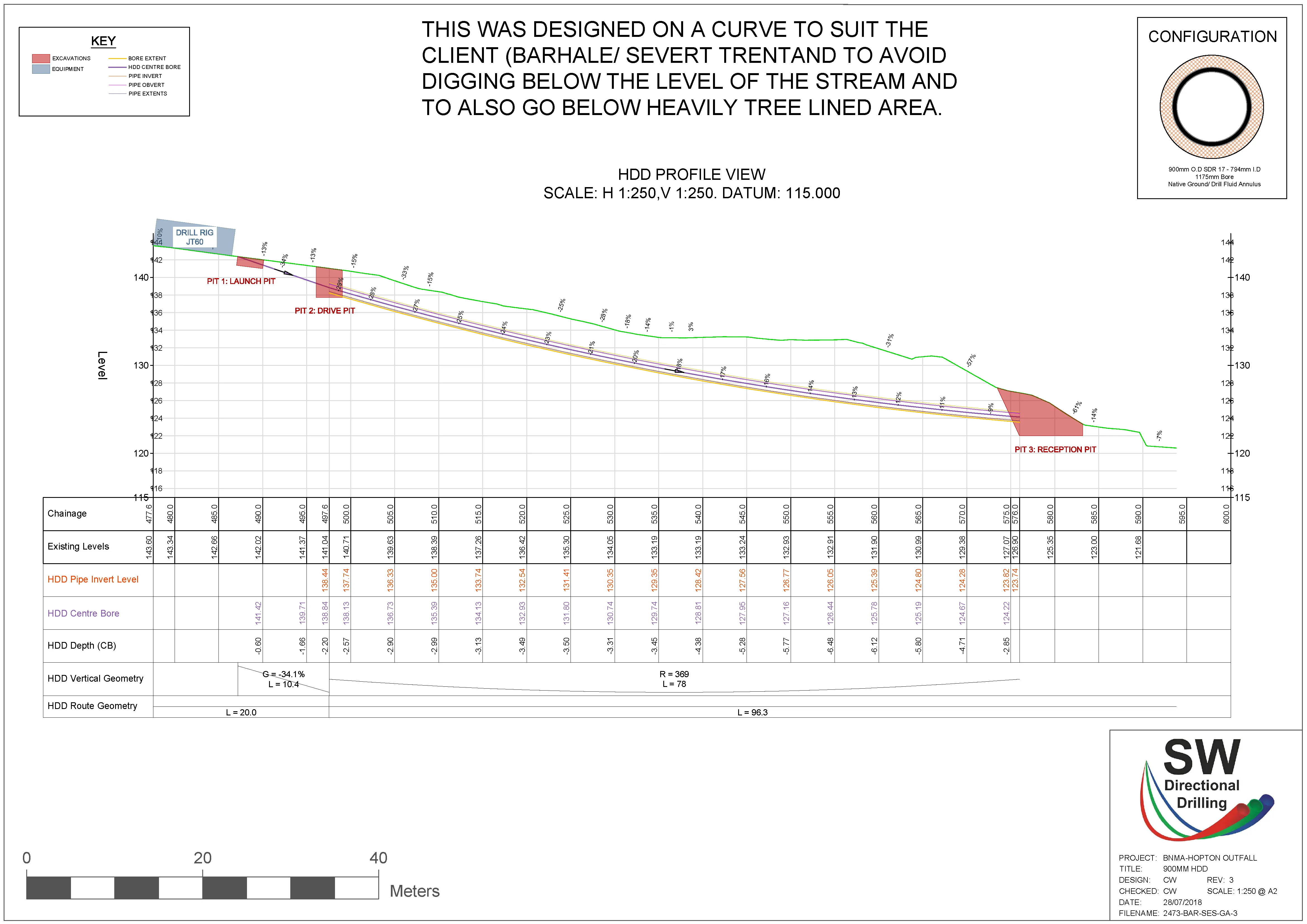
| Long-section profile | Bore path drawn to falls, with depth, radius & cover at every chainage |
|---|---|
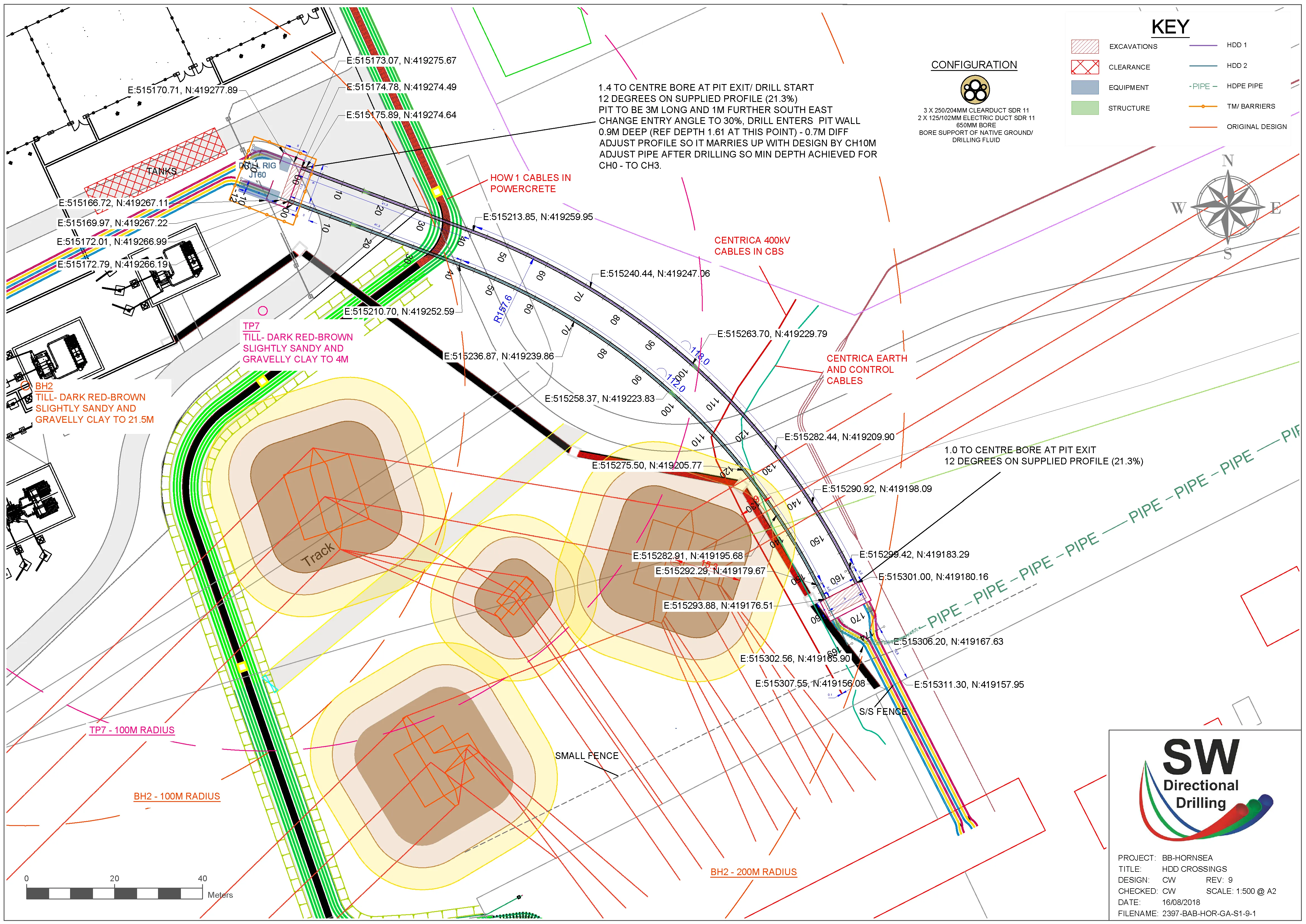
| Plan / site layout | Launch & reception positions, line, existing services, working areas |
| Settlement design | Ground-movement & pipe-loading assessment (e.g. National Highways CD 622) |
| Approval submissions | Network Rail asset protection (NR/L2/CIV/044) & highways packs |
| Watercourse crossings | Designed to Environment Agency FRA3 (min 1.5m below the bed), applied to every watercourse crossing |
| Surface monitoring | Pre-works baseline survey & monitoring through the works (CD 622 / Network Rail) |
| Software | AutoCAD & Civil 3D |
| As-builts | The line as actually drilled, recorded back onto the drawing |
Each crossing is assessed on its own cover, diameter and ground, not to a single generic figure.
Real drawings
These are two of our own drawings. The first is a long-section profile, the side-on view that sets the bore to its depth and falls. The second is a plan layout, showing the line threaded past the existing services and structures on site.
Questions answered
We design it ourselves, in-house. The same people who run the rig set the bore out, so the design is grounded in what the machine and the ground will actually do rather than a theoretical line on a drawing. You get a long-section profile and a plan layout for every crossing, and we are happy to work to your engineer's drawings instead if you already have them.
Yes. We carry out settlement, heave and pipe-loading assessments where a crossing needs them. For crossings under National Highways motorways and trunk roads that work follows the DMRB standard CD 622, Managing geotechnical risk, which covers trenchless crossings and sets out how the predicted ground settlement and heave are calculated, mitigated and signed off. Each crossing gets its own assessment rather than a single generic figure, because the cover, diameter and ground change from one bore to the next.
Yes. We prepare the asset-protection drawings and submissions these authorities ask for. Under the railway that means working to Network Rail NR/L2/CIV/044. Under the strategic road network the crossing is designed and reported under CD 622 and certified by National Highways before construction can start, and it sits alongside the street-works consents for the motorway. Tell us the asset owner and we will produce the pack in the format they expect.
We design it to the Environment Agency standard for drilling beneath a main river, exemption FRA3. That keeps the bore at least 1.5m below the bed for its whole length and for 5m beyond each bank, within 10 degrees of perpendicular to the flow, with the launch and reception pits set back from the bank. A statutory main river is one shown on the Environment Agency main river map. Many watercourses are not main rivers and would not strictly need it, but we apply the same minimum standard to every watercourse crossing, so the design is sound whatever the channel. The bed levels the design needs come from a bathymetric survey of the watercourse, which we can carry out as part of the topographical survey.
Yes. Under National Highways CD 622 the carriageway surface over a crossing is monitored before, during and after the works, against a baseline survey taken before drilling starts. We set up that pre-works baseline and the grid of survey points, then monitor through the job against the agreed trigger levels, so the actual ground movement is checked against the predicted settlement the whole way. Network Rail crossings are monitored in much the same way.
Yes. We record the line as actually drilled back onto the drawing so you have an accurate as-built for your records and for anyone working near the route in future.
Related services
An earlier-stage look at whether a route can be drilled at all, before the detailed design.
View service →The measured ground and levels the bore design is set out from.
View service →The installation the design exists to make buildable.
View service →Send us your levels, the line you want and the asset owner, and we'll come back with a bore profile, a layout and a budget price.